在之前的教程中我们学习了网络地址转换。我们可以发现,这种转换是一对一转换形式,如果内网中有多个终端如何解决?今天我们学习一下动态网络地址转换。
基本配置
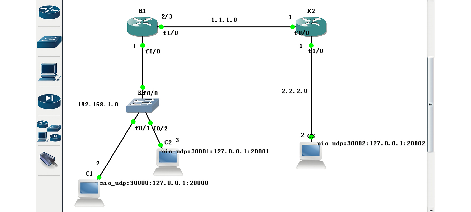
首先我们需要配置一下网络环境,如图配置好每台设备的网络地址,其中 R1 路由器的 f1/0 端口需要设置多 IP,还需在此端口设置默认路由:
1
2
3
4
5
6
7
8
9
10
11
| R1#configure terminal
R1(config)#interface fastEthernet 0/0
R1(config-if)#ip address 192.168.1.1 255.255.255.0
R1(config-if)#no shutdown
R1(config-if)#exit
R1(config)#interface fastEthernet 1/0
R1(config-if)#ip address 1.1.1.2 255.255.255.0
R1(config-if)#ip address 1.1.1.3 255.255.255.0 secondary
R1(config-if)#no shutdown
R1(config-if)#exit
R1(config)#ip route 0.0.0.0 0.0.0.0 fastEthernet 1/0
|
接下来我们设置 R2 路由,无需过多设置,简单配置各端口 IP 即可:
1
2
3
4
5
6
7
8
| R2#configure terminal
R2(config)#interface fastEthernet 0/0
R2(config-if)#ip address 1.1.1.1 255.255.255.0
R2(config-if)#no shutdown
R2(config-if)#exit
R2(config)#interface fastEthernet 1/0
R2(config-if)#ip address 2.2.2.1 255.255.255.0
R2(config-if)#no shutdown
|
转换配置
1
2
3
4
5
6
7
8
| R1(config)#access-list 1 permit 192.168.1.0 0.0.0.255
R1(config)#ip nat pool cjk 1.1.1.2 1.1.1.3 netmask 255.255.255.0
R1(config)#ip nat inside source list 1 pool cjk
R1(config)#interface fastEthernet 0/0
R1(config-if)#ip nat inside
R1(config-if)#exit
R1(config)#interface fastEthernet 1/0
R1(config-if)#ip nat outside
|
注意:我们开始在 R1 设置动态网络地址转换。
综合测试
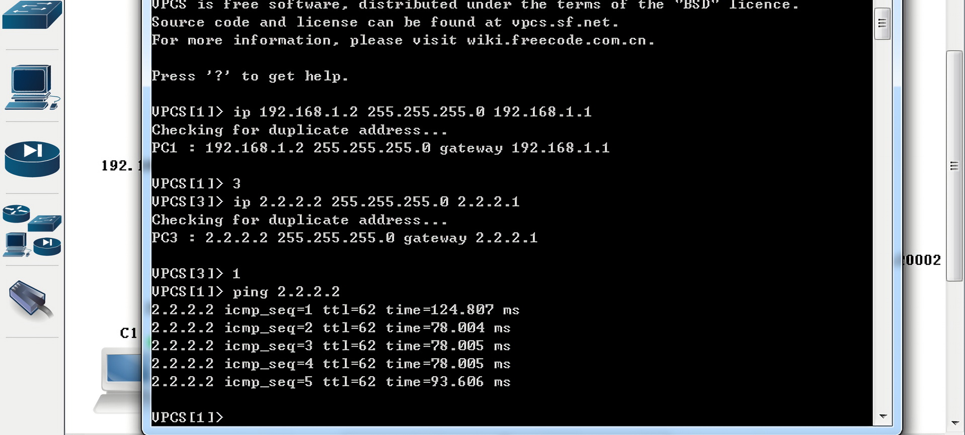
最后测试一下:
C1 已经可以和 C3 通信了,那 C2 是否可以?我们在 R2 上加入 ACL 限制 C2 的地址:
1
2
3
4
| R2(config)#access-list 1 deny host 192.168.1.3
R2(config)#access-list 1 permit any
R2(config)#interface fastEthernet 0/0
R2(config-if)#ip access-group 1 in
|
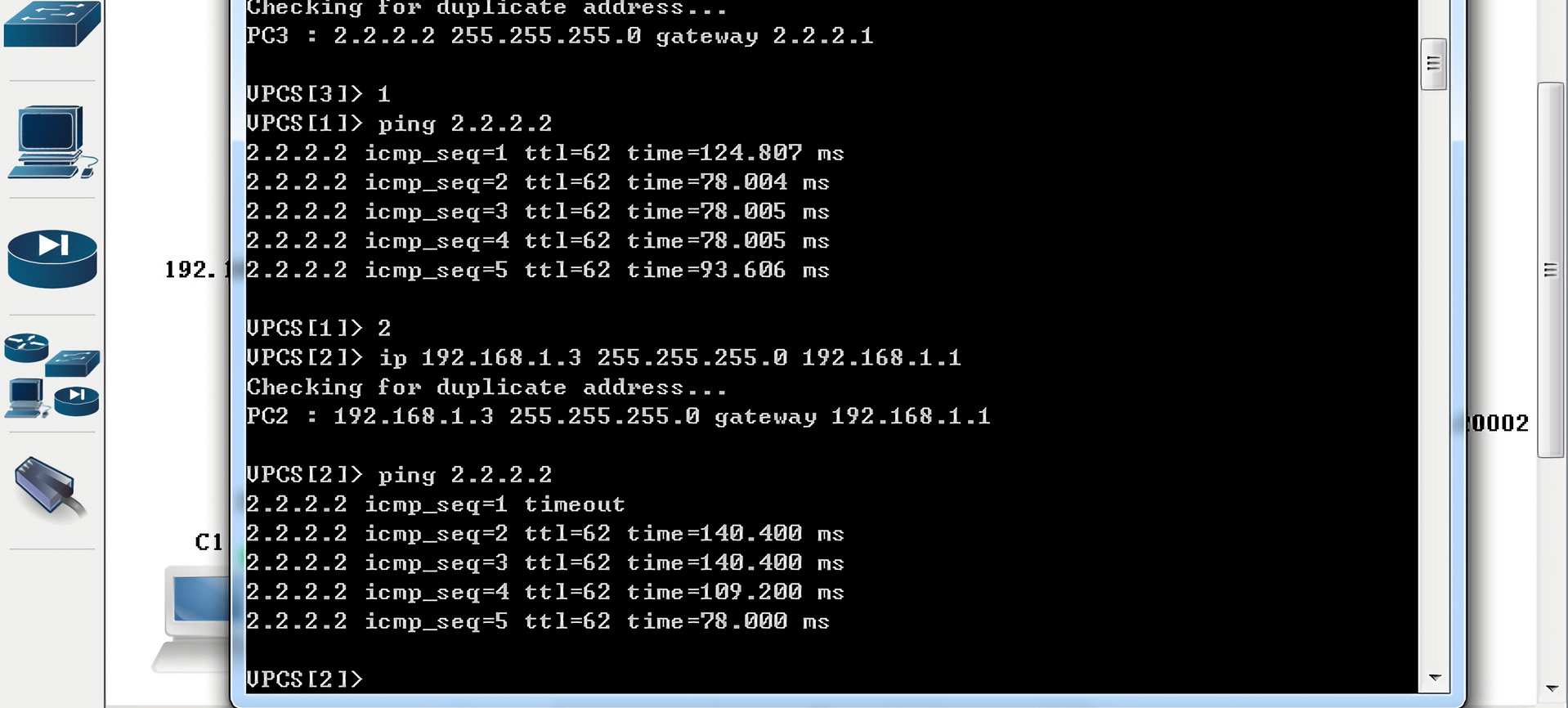
然后再测试 C2 去 Ping 通 C3:
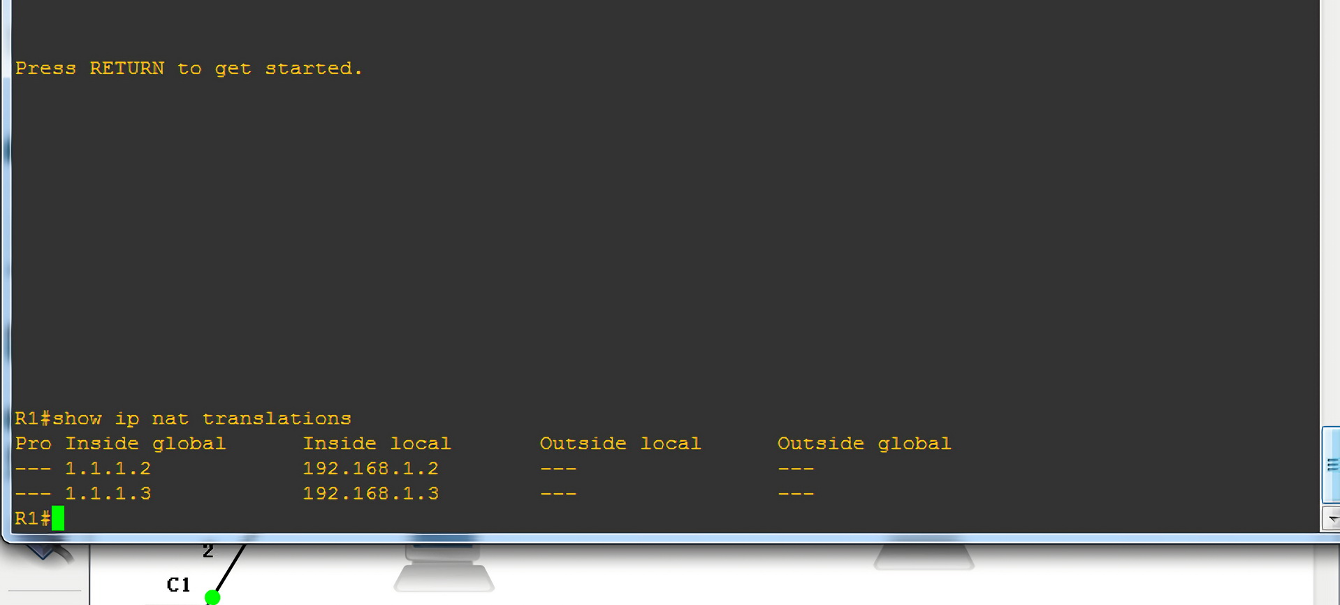
我们查看的 NAT 列表:


条评论